At Zenlayer, we’re at the forefront of infrastructure innovation. With over 300 Points of Presence (POPs) boasting a staggering 130Tbps of aggregated IP capacity, we have a unique vantage point on industry trends. One of the most exciting developments is the surge in popularity of 100Gbps input/output (I/O) server systems.
This shift is driven by a diverse range of customers. For example: content delivery networks (CDNs) are pushing the boundaries of network efficiency, striving to squeeze every last bit of data through the pipeline; video streaming providers are demanding ever-faster processing and rendering capabilities for high-resolution content; and high-performance computing (HPC) applications are constantly seeking ways to overcome bandwidth limitations and minimize latency.
Building on our previous piece, The 100G server revolution – the bandwidth breakthrough, this article takes a deeper dive into this trend, exploring design considerations for server systems and strategies that can unlock the full potential of 100Gbps I/O.
Data flow in modern servers – why go NVMe?
Technically, the CPU directly communicates with memory through its memory controller, and with PCIe devices through its PCIe controller. These are the primary communication channels for data transfer.
Consider a scenario where you keep large amounts of data on SATA SSDs and need to locate a file and transfer its contents to the network—here’s where things get interesting: the CPU doesn’t talk directly to hard drives connected to SAS/SATA channels.
How then does data flow to and from SAS/SATA Drives? The answer is SAS/SATA controllers, specialized hardware components that manage communication between the CPU and storage devices like hard drives and SSDs. These controllers handle tasks like translating commands from the CPU into a format understood by storage devices, checking for errors, and optimizing data transfer, while often affording RAID redundancy capabilities for those same drives.
Hard disk drives (HDDs) and solid-state drives (SSDs) were the mainstays of storage for a long time, until NVMe SSDs came onto the scene offering a significant leap in I/O speeds. NVMe uses the PCIe bus to communicate directly with the CPU, eliminating the bottleneck of traditional SAS/SATA controllers. This makes NVMe SSDs a perfect choice for building high-performance 100GbE servers.
Memory access architectures: UMA vs. NUMA
Aside from the booming popularity of NVMe SSDs for high I/O, server systems also rely on memory to store data and instructions for processing. How processors access this memory can significantly impact performance. Here, we explore two main memory access architectures: Uniform Memory Access (UMA) and Non-Uniform Memory Access (NUMA).
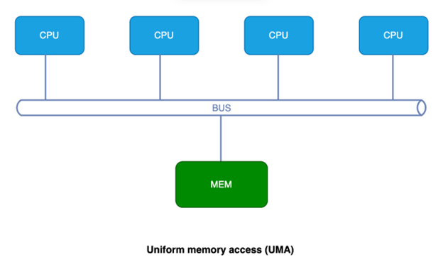
Uniform memory access (UMA):
- Equal access time: In a UMA system, all processors have the same access time to any memory location, regardless of the processor’s physical location or the memory module holding the data.
- Simple design: UMA architectures are typically simpler to design and manage as there’s a single pool of shared memory readily accessible to all processors. However, as the number of processors increases in a UMA system, the shared memory bus can become a bottleneck, limiting overall performance due to increased competition for memory access. So, UMA is well-suited for smaller systems with a few processors or for applications where consistent memory access latency is critical.
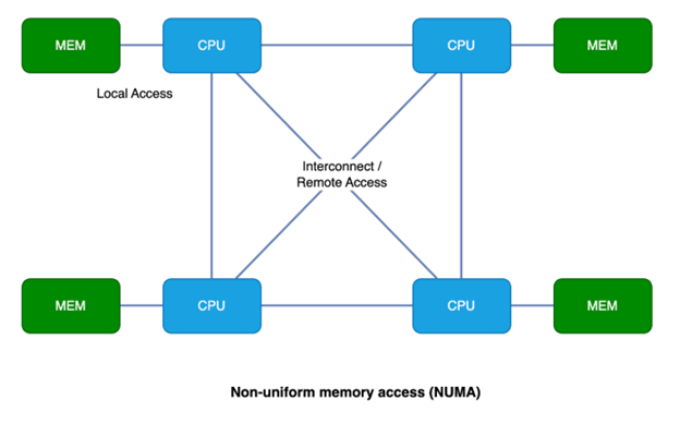
Non-uniform memory access (NUMA):
- Local vs. remote memory: In a NUMA system, each processor has its own local memory pool that it can access with the lowest latency. Accessing memory from another processor’s local memory takes longer, creating a non-uniform access time.
- Scalability benefits: NUMA architectures can scale better with more processors because they distribute memory resources, reducing contention on a single memory bus. However, optimizing application performance in a NUMA system requires careful consideration of data locality, where data is stored relative to the processor that needs it most.
- Use case: NUMA is ideal for larger multi-processor systems where high performance and scalability are crucial. Real-time data analytics, high-performance computing, and large virtualized environments often benefit from NUMA architecture.
Optimizing data flow for high-performance systems
We’ve identified the key players in a high-performance system: CPU, memory, network adapter (via PCIe), and NVMe SSDs (via PCIe). Now, let’s explore how data flows between these components to achieve the fastest possible speeds, especially considering 100G network connections, here are some strategies:
- Data locality: Keep frequently accessed data in the fastest available location, prioritizing keeping crucial data in RAM for the quickest access. Less frequently used data can reside on NVMe drives. In NUMA systems, data locality becomes even more critical. Ideally, frequently accessed data should reside in the same NUMA node as the CPU core that needs it most.
- “Non-blocking” PCIe bandwidth: Calculate the combined bandwidth required by your NVMe drives and network adapters. Ensure the server utilizes a non-blocking PCIe slot configuration to handle this data transfer without bottlenecks.
- Software optimization: Modern operating systems and applications can be optimized to leverage multiple cores and data locality principles. This can involve techniques like memory caching and NUMA-aware memory allocation, ensuring data is accessed from the fastest available source.
Case study 1: Single-socket server configuration
Let’s start with a single-socket server system, for example, a Dell PowerEdge R7515, outfitted with one AMD EPYC 9254 CPU with 24 cores / 48 threads. Since this is a single-socket system, the concept of UMA and NUMA doesn’t come into play.
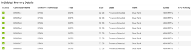
For the memory configuration, we’ve opted for 8x 32GB dual rank DDR5 memory sticks, offering a total capacity of 256GB and a speed of 4800 MT/s. This translates to a memory-to-core ratio of 256GB / 24 cores = 10.67 GB/core, which is significantly higher than the typical 8:1 ratio found in standard memory-enhanced cloud server configurations.
The R7515 can support configurations with either 12x NVMe drives or 24x NVMe drives. We’ll use the 12x NVMe drive configuration as an example. As each NVMe drive utilizes 4x PCIe lanes, 12x NVMe drives require 12 * 4 = 48 PCIe lanes for a non-blocking design. Selecting 3 x16 backplane to system board cables fulfils this requirement. The 12x NVMe drives to CPU mapping diagram is shown here:
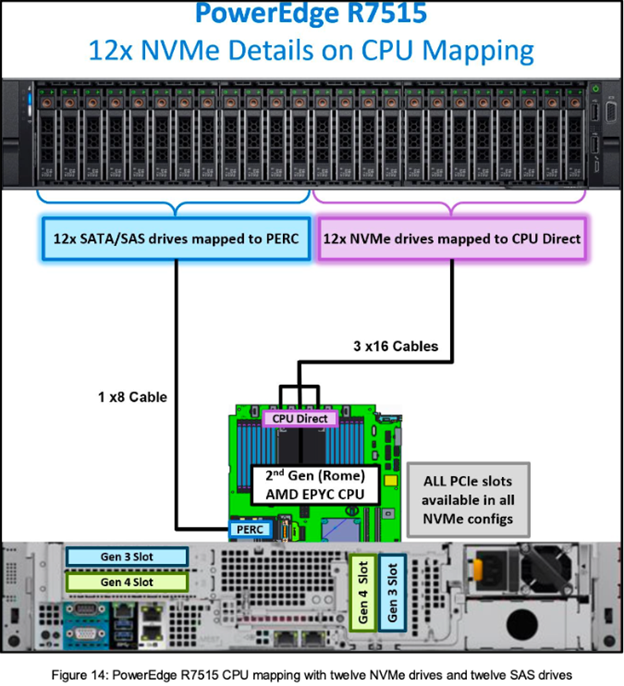 Ref: https://downloads.dell.com/manuals/common/dellemc-nvme-io-topologies-poweredge.pdf
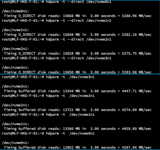
To gather performance benchmarks, we conducted speed tests on the NVMe SSDs to verify their performance. Using hdparm for direct disk reads, the results showed speeds of around 5.2 GB/s. Buffered disk reads yielded speeds of around 4.4 GB/s. These results are consistent with our expectations for this NVMe SSD configuration:
When we look into the network adapter options, the AMD EPYC 9254 CPU offers a PCIe capacity of PCIe 5.0 x128. If we look into the PCIe link performance comparison table here, a 100Gbps I/O via a single network adapter slot will require:
- PCIe v3.0: x16 or higher
- PCIe v4.0: x8 or higher
- PCie v5.0: x4 or higher
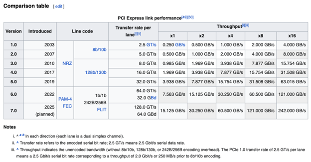 Ref: PCI Express
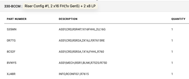
To accommodate future upgrades, the server is equipped with riser configuration #1. This configuration offers 4 PCIe slots, including 1 x16 Gen 5, 1 x16 Gen 4, and 2 x8 Gen 4, providing the necessary bandwidth for demanding expansion cards.
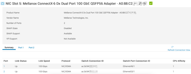
We installed a Mellanox ConnectX-6 dual port network adapter in PCIe slot-5. This slot is a Gen4 x16 port, offering a theoretical bandwidth of 256GT/s. In a single-socket system like this, the CPU affinity value (which is “1” here) doesn’t have much relevance since there’s only one CPU. CPU affinity becomes important in NUMA systems with multiple CPUs, where it helps identify the specific CPU a PCIe device is connected to:
By utilizing a single-CPU configuration and strategically allocating PCIe lanes using a non-blocking approach, we’ve designed a system capable of handling at least 100Gbps of I/O throughput.
Case study 2: Dual-socket server configuration
Remember that NUMA diagram? NUMA is primarily concerned with memory access, but how does PCIe fit into its design?
As we touched on earlier in this article, the CPU directly communicates with memory through its memory controller, and with PCIe devices through its PCIe controller. Each CPU in a multi-socket system has its own set of PCIe lanes. Devices connected to these lanes are only accessible by the specific CPU they’re attached to. Since NVMe drives are running over PCIe, they’re naturally designed to connect directly to a CPU’s PCIe lanes for optimal performance. See the diagram below for a NUMA system with PCIe in place.
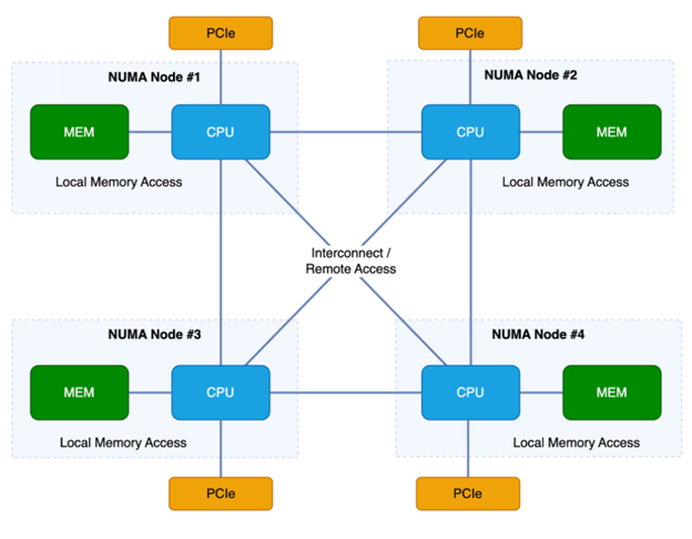
So, the picture is clear: for best performance, try to keep data local to the NUMA node it’s being processed on and the directly attached PCIe device whenever possible.
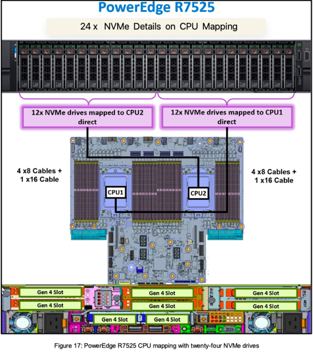
Consider the Dell PowerEdge R7525 server, a 2U configuration that supports a staggering 24 NVMe drives. The first 12 drives are directly connected to CPU2, while the remaining 12 connect directly to CPU1. Each set of 12 drives utilizes a combination of 4 x8 PCIe cables and 1 x16 cable, providing a non-blocking path of 48 lanes to the corresponding CPU (each NVMe uses 4x PCIe lanes). This highlights the importance of NUMA-aware allocation, as detailed in the following NVMe and CPU mapping diagram:
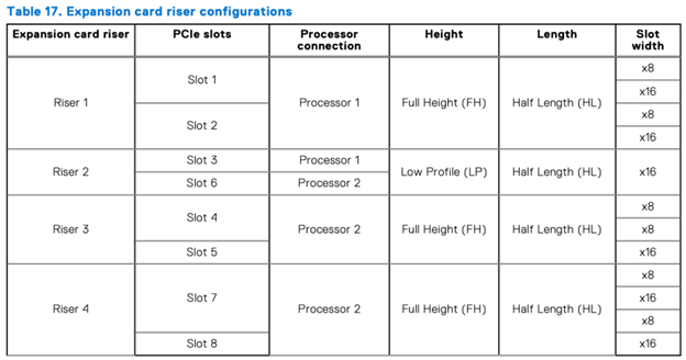
To maximize performance for your Dell PowerEdge R7525 server, consider the following when installing network adapters in the PCIe slots:
- Matching network adapters to CPU: For best performance, install network adapters in the PCIe slots that correspond to the CPU your NVMe drives are connected to. You can find this mapping in the riser configuration table provided by Dell.
- Slot selection and bandwidth: Refer to the “slot width” information in this riser configuration table to choose appropriate slots based on the bandwidth requirements of your network adapters:
 Ref: Dell PowerEdge R7525 Installation and Service Manual | Dell US
Here’s a breakdown of the NVMe and network adapter slot recommendations (based on the table shown above):
- NVMe drives (first 12 trays): These connect to CPU2. For network adapters associated with these drives, choose slots 4/5/6/7/8.
- NVMe drives (last 12 trays): These connect to CPU1. For network adapters associated with these drives, choose slots 1/2/3.
By following these guidelines, you can ensure that your network adapters and NVMe drives leverage the closest CPU and memory resources, minimizing latency and maximizing performance.
Final thoughts
I hope this guide helps provide a foundation for understanding hardware design considerations when choosing and designing a 100G server. Optimal configuration hinges on your specific needs. For both single and multi-CPU systems, maximizing I/O performance often involves strategically placing components to minimize data transfer latency.
- Single-CPU systems: These offer a simpler setup. Calculate the combined bandwidth requirements for your NVMe drives and network adapters. Design the data path for maximum throughput, including NVMe PCIe lanes, network adapter PCIe lanes, and overall PCIe bandwidth. Select hardware that meets your I/O performance demands.
- Multi-CPU systems: NUMA-aware allocation is crucial. Prioritize keeping data processing and movement within the same NUMA node and its associated PCIe lanes. This maximizes performance from your server hardware.
Please note that while other technologies like direct memory access (DMA) can optimize data transfer, achieving optimal performance also requires software to be tuned for the specific NUMA design.
If you found this helpful, I’ll be talking about server latency in the next piece – stay tuned!